Home › Unlabelled ›
Diagram Of A Series Circuit / Parallel And Series Circuits For Elementary School Google Search Series And Parallel Circuits Circuit Drawing Elementary Schools - In some cases a diagonal line may be used which is placed at 45 degrees.
Diagram Of A Series Circuit / Parallel And Series Circuits For Elementary School Google Search Series And Parallel Circuits Circuit Drawing Elementary Schools - In some cases a diagonal line may be used which is placed at 45 degrees.. The following are general circuit diagram rules. There are two basic ways in which to connect more than two circuit components: The phasor diagram for a series rlc circuit is produced by combining together the three individual phasors above and adding these voltages vectorially. This is the third principle of series circuits: Construct a simple and complex series circuit.
Sneak a peek at figure 1. The lamps are strung together end to end. Draw circuit diagrams to show the correct positions of an ammeter in … In a series connection, components are connected end to end, so that current flows first through one, then through the other. In the series connection, the current goes through one lamp and then the other.
Series Parallel Circuits Department Of Chemical Engineering And Biotechnology from www.ceb.cam.ac.uk That's the key difference between series and parallel!. In a series connection, components are connected end to end, so that current flows first through one, then through the other. Steps to draw a phasor diagram. Since the current is everywhere the same within a series circuit, the i value of δv = i • r is the same in each of the resistors of a series circuit. Two components are in series if they share a common node and if the same. Jonny nelson introduces an animated explanation of circuits. Voltage drop in resistance vr = ir is taken in phase with the current vector; The supply voltage in a series circuit is equal to the sum of the individual voltage drops.
The phasor diagram of the rc series circuit is shown below:
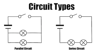
Series, parallel, ammeter, current, by the end of this lesson you will be able to: The lamps are strung together end to end. Even though there is a break, the change in electric potential around this loop still has to be zero volts. In the interactive box (applet) below, you will need … So for example, in the case of dc, the circuits can also be divided into three groups, such as series dc circuit, parallel dc circuit, and. Construct a simple and complex series circuit. For our comparison of series vs parallel circuits, let's start by talking about the simplest circuit of all — the series circuit. A) identify all the elements in this circuit diagram. Rlc series circuit when a pure resistance of r ohms, a pure inductance of l henry and a pure capacitance of c farads are connected together in series combination with each other then rlc series circuit is formed. Two components are in series if they share a common node and if the same. The two simplest of these are called series and parallel and occur frequently. This causes the bulb to light, the solenoid to be activated and the motor's spindle to rotate. As all the three elements are connected in series so, the current flowing through each element of the circuit will be the same as the total current i flowing in the circuit.
The following are general circuit diagram rules. The two simplest of these are called series and parallel and occur frequently. In series circuits, electrical components. Sneak a peek at figure 1. Try building this simple series circuit.
Series And Parallel Circuits Wikipedia from upload.wikimedia.org Component symbols in a circuit diagram are usually placed horizontally or vertically. Two components are in series if they share a common node and if the same. As all the three elements are connected in series so, the current flowing through each element of the circuit will be the same as the total current i flowing in the circuit. In some cases a diagonal line may be used which is placed at 45 degrees. Here we have a series circuit with a battery, an led and a resistor. In the series connection, the current goes through one lamp and then the other. So the voltage drop (δv) will vary with varying resistance. Thus, all devices along the circuit stop working at the same time.
You will notice from the diagram that 1 amp continually flows through the circuit.
Resistors in series with a break in the circuit. Therefore, a series circuit has the same current at all points in the circuit. The battery creates the current in the circuit. Another major defect of series lighting circuit is that as all lamps or bulbs are connected between line l and neutral n accordingly, if one of the light bulb gets faulty, the rest of the circuit will not work as the circuit will be open as shown in fig below. The supply voltage in a series circuit is equal to the sum of the individual voltage drops. Here, we have three resistors (labeled r 1, r 2, and r 3) connected in a long chain from one terminal of the battery to the other. Series vs parallel circuits series vs parallel: One drawback of series connections is that if one component fails in a way that results in an open circuit, the entire circuit is broken and none of. Take the current i (r.m.s value) as a reference vector; A) identify all the elements in this circuit diagram. In some cases a diagonal line may be used which is placed at 45 degrees. In a series rc circuit, the total opposition or impedance is due to a combination of both resistance (r) and capacitive The following are general circuit diagram rules.
Even though there is a break, the change in electric potential around this loop still has to be zero volts. The components of the electrical dc circuit are mainly resistive, whereas components of the ac circuit may be reactive as well as resistive. There are two basic ways in which to connect more than two circuit components: This causes the bulb to light, the solenoid to be activated and the motor's spindle to rotate. Wires connect the other components of the circuit.
Simple Circuit Diagram For Kids Wiring Diagram Mute Wiper F Mute Wiper F Bujinkan It from study.com A series circuit is a closed circuit where the current follows one path. The lamps are strung together end to end. Here, you can see there is a cut in the line wire connected to lamp 3, so the bulb is switch off and the rest circuit is working. Sneak a peek at figure 1. The two light bulbs will produce light, because the circuit is unbroken. The voltage drops across each component of the series … Resistors in series with a break in the circuit. A series circuit is a circuit that only has one path for the c… in the series circuit the components are placed in a continuou… the current throughout the series circuit is the same everywhe…
This is often labeled on your circuit diagram, next to two or more parallel lines of different length.
A series circuit is one in which every component is arranged in a series connection. Another major defect of series lighting circuit is that as all lamps or bulbs are connected between line l and neutral n accordingly, if one of the light bulb gets faulty, the rest of the circuit will not work as the circuit will be open as shown in fig below. In a series connection, components are connected end to end, so that current flows first through one, then through the other. The total opposition to current flow in any ac circuit is called impedance. Wires connect the other components of the circuit. Series circuits are useful if you want a warning that one of the components in. There are two basic ways in which to connect more than two circuit components: This will help in calculating circuit values using ohm's law. So the voltage drop (δv) will vary with varying resistance. In the series connection, the current goes through one lamp and then the other. Sneak a peek at figure 1. One drawback of series connections is that if one component fails in a way that results in an open circuit, the entire circuit is broken and none of. Figure 1 series rl circuit diagram.