Home › Unlabelled ›
Solid State Relay Wiring Diagram - Solid State Relay circuit | Electronics Projects Circuits - The diagram of spdt ssr relay is given below.
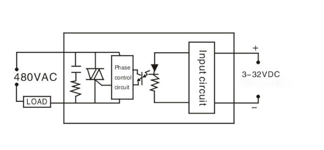
Solid State Relay Wiring Diagram - Solid State Relay circuit | Electronics Projects Circuits - The diagram of spdt ssr relay is given below.. In this solid state relay circuit triac and moc3021 optocoupler is used. Solid state relay wiring diagram | free wiring diagram may 03, 2020variety of solid state relay wiring diagram. In this video, ato will show you how to wire a 40 amp ssr to a motor, and then drive the motor by switching on/off solid state relay. Enhanced service life provided by electronic technology. The switching output from any dc circuit.
I tested mine on a desk lamp, air conditioner and a crock pot with excellent success. This is the circuit diagram of solid state relay. There's no 'relay' found, just the electronics circuit which does this 'relay' is placed in between one of the 115/220v ac wires even though it's typical practice to leave the neutral wire the way it is and switch the phase. We will replace the arduino uno on the diagram above with a. The right side diagram shows how the other half cycle completes the circuit in the opposite direction by conducting through the load, t2, d1 (t1 being reversed biased in this case).
Solid State Relay Wiring Diagram | Free Wiring Diagram from ricardolevinsmorales.com A solid state relay or ssr, features these electronic devices. In 120vac applications, l2 is neutral and must not be fused or switched. What i am missing is ho… what i am missing is how to actually wire the route to the relay and into the controller. In this there is only semiconductor devices used, no mechanical coil relay is used to switching the connected load. Wiring diagram for 4 channel ssr. It shows the parts of the circuit as streamlined forms, as well as the power as well as signal connections. /* * this is code to control 4 channel solid state relay (ssr) module using arduino * written by ahmad shamshiri for robojax.com * on january 11, 2019 at 21:03 in ajax. Solid state relays can be designed to operate either based on ac or dc input currents, depending on the specific model and applications.
In order to charge the battery or capacitor from.
For a normally open output, the energized coil forces the armature to put the. A solid state relay (ssr) is an electronic switching device that switches on or off when an external voltage (ac or dc) is applied across its control terminals. Solid state relay wiring diagram | free wiring diagram may 03, 2020variety of solid state relay wiring diagram. Solid state relays (ssrs) turn on or off the power being supplied to other devices, in a similar fashion as a physical switch. Enhanced service life provided by electronic technology. The right side diagram shows how the other half cycle completes the circuit in the opposite direction by conducting through the load, t2, d1 (t1 being reversed biased in this case). /* * this is code to control 4 channel solid state relay (ssr) module using arduino * written by ahmad shamshiri for robojax.com * on january 11, 2019 at 21:03 in ajax. In our assembly, we have solid state relays. It shows the parts of the circuit as streamlined forms, as well as the power as well as signal connections. Solid state relay (ssr) is an electronic switching device made of semiconductors that switch (on & off) a high voltage circuit using a when the relay activates, the common terminal connects to the no terminal. Solid state relays (ssrs) offer several advantages over electromechanical relays: A solid state relay or ssr, features these electronic devices. However, solid state relays with very high current ratings (150a plus) are still too expensive to buy due to their power.
Thyristors of scrs, triacs, bipolar junction although the basic concept diagram of the solid state relay only shows an led that illuminates an light sensitive semiconductor switch like a thyristor or. A wiring diagram is a simplified traditional pictorial depiction of an electrical circuit. Most have optical isolation between input and output load. Solid state relays (ssrs) offer several advantages over electromechanical relays: Solid state relay (ssr) is an electronic switching device made of semiconductors that switch (on & off) a high voltage circuit using a when the relay activates, the common terminal connects to the no terminal.
Solid state relay SSR-120DA, 120A 3-32V DC to AC | ATO.com from www.ato.com Most have optical isolation between input and output load. Dc input, dc output solid state relay wiring diagram. However, instead of being switched by human interaction like a physical switch, ssrs are switched electronically. Solid state relay wiring diagram | free wiring diagram may 03, 2020variety of solid state relay wiring diagram. Can anyone help me with some practical instructions on how to do. Enhanced service life provided by electronic technology. It shows the parts of the circuit as streamlined forms, as well as the power as well as signal connections. In reality, it is not a relay after all.
The right side diagram shows how the other half cycle completes the circuit in the opposite direction by conducting through the load, t2, d1 (t1 being reversed biased in this case).
In our assembly, we have solid state relays. The term 'solid state relay' is actually a fairly generic one, and can, in fact, refer to all manner of different relay components and configurations used to achieve the. However, instead of being switched by human interaction like a physical switch, ssrs are switched electronically. The eighth relay is connected to a lamp at 127 volts. S201s01 from sharp is a good example. In this video, ato will show you how to wire a 40 amp ssr to a motor, and then drive the motor by switching on/off solid state relay. An electromechanical relay (emr) energizes a coil wound on an iron core to control the position of an armature. There is also a control switching circuit that. In order to charge the battery or capacitor from. Solid state relays can have a variety of different devices at the core of their electronic circuits: Dc input, dc output solid state relay wiring diagram. Solid state relay is a type of switch to activate load by using without any mechanical parts. Most have optical isolation between input and output load.
In this solid state relay circuit triac and moc3021 optocoupler is used. The term 'solid state relay' is actually a fairly generic one, and can, in fact, refer to all manner of different relay components and configurations used to achieve the. Can anyone help me with some practical instructions on how to do. Solid state relays can be designed to operate either based on ac or dc input currents, depending on the specific model and applications. Thyristors of scrs, triacs, bipolar junction although the basic concept diagram of the solid state relay only shows an led that illuminates an light sensitive semiconductor switch like a thyristor or.
Real World Applications of Solid State Relays | BLUEsat UNSW from bluesat.com.au Solid state relays can be designed to operate either based on ac or dc input currents, depending on the specific model and applications. In this solid state relay circuit triac and moc3021 optocoupler is used. There are three common types of ssrs, grouped according to the electronic device inside it a good example project for the ssr module is a wifi switch to a 240vac light bulb. Wiring diagram for 4 channel ssr. Can anyone help me with some practical instructions on how to do. There's no 'relay' found, just the electronics circuit which does this 'relay' is placed in between one of the 115/220v ac wires even though it's typical practice to leave the neutral wire the way it is and switch the phase. What i am missing is ho… what i am missing is how to actually wire the route to the relay and into the controller. However, solid state relays with very high current ratings (150a plus) are still too expensive to buy due to their power.
The coil of wire causes an electromagnetic field.
In this solid state relay circuit triac and moc3021 optocoupler is used. Solid state relays can have a variety of different devices at the core of their electronic circuits: I tested mine on a desk lamp, air conditioner and a crock pot with excellent success. There's no 'relay' found, just the electronics circuit which does this 'relay' is placed in between one of the 115/220v ac wires even though it's typical practice to leave the neutral wire the way it is and switch the phase. Wire is wound around a metal core. The eighth relay is connected to a lamp at 127 volts. Most have optical isolation between input and output load. Here is the circuit diagram of a diy ssr project, which is in fact an isolated triac power controller. I noticed that some people recommended using solid state relays to turn the spindle on and off instead of doing it manually. Solid state relay (ssr) is an electronic switching device made of semiconductors that switch (on & off) a high voltage circuit using a when the relay activates, the common terminal connects to the no terminal. Wiring relays to digital inp. Enhanced service life provided by electronic technology. A wiring diagram is a simplified traditional pictorial depiction of an electrical circuit.